Node.js Raspberry Pi RGB LED with WebSocket
Using Pulse-Width Modulation
In the previous chapters we have learned how to use WebSocket, and how to use GPIO to turn LEDs on and off.
In this we will use chapter we use a RGB LED, with PWM (Pulse-width modulation) to display different colors based on user input via WebSocket.
An RGB LED is a LED with 3 different colors. It has a RED, GREEN and BLUE LED (RGB LED).
And using PWM, we can set the individual strength of the 3 LEDs. This will allow us to mix them, to set a color.
What do we need?
In this chapter we will create an example where we control an RGB LED with a web page via WebSocket.
For this you need:
- A Raspberry Pi with Raspian, internet, SSH, with Node.js installed
- The pigpio module for Node.js
- The socket.io module for Node.js
- 1 x Breadboard
- 3 x 220 Ohm resistor
- 1 x RGB LED (common anode or common cathode)
- 4 x Female to male jumper wires
Click the links in the list above for descriptions of the different components.
Note: The resistor you need can be different from what we use depending on the type of LED you use. Most small LEDs only need a small resistor, around 200-500 ohms. It is generally not critical what exact value you use, but the smaller the value of the resistor, the brighter the LED will shine.
Install the pigpio Module
Earlier, we have used the "onoff" module, which works great for just turning on and off. Now we want to set the set the strength of the LEDs, so we need a GPIO Module with a bit more functionality.
We will use the "pigpio" Node.js module, as this allows for PWM.
With PWM we can set the strength of a LED from 0 to 255.
The "pigpio" Node.js module is based on the pigpio C library.
If you are using the "Lite" version of Raspbian, this is most likely not included and must be manually installed.
Update your system package list:
pi@w3demopi:~ $ sudo apt-get update
Install the pigpio C library:
pi@w3demopi:~ $ sudo apt-get install pigpio
Now we can install the "pigpio" Node.js module using npm:
pi@w3demopi:~ $ npm install pigpio
Now the "pigpio" module should be installed and we can use it to interact with the GPIO of the Raspberry Pi.
Note: Since the "pigpio" module uses the pigpio C library, it requires root/sudo privileges to access hardware peripherals (like the GPIO).
Building the Circuit
Now it is time to build the circuit on our Breadboard.
If you are new to electronics, we recommend you turn off the power for the Raspberry Pi. And use an anti-static mat or a grounding strap to avoid damaging it.
Shut down the Raspberry Pi properly with the command:
pi@w3demopi:~ $ sudo shutdown -h now
After the LEDs stop blinking on the Raspberry Pi, then pull out the power plug from the Raspberry Pi (or turn of the power strip it is connected to).
Just pulling the plug without shutting down properly may cause corruption of the memory card.
In building this Circuit it is important to know if you have a common anode, or common cathode, RGB LED:
You can check with your provider, or test it yourself:
Connect cables to GND and 3.3V pin. Connect GND to the longest leg of the RGB LED and the 3.3 V to any other leg. If the it lights up, your RGB LED has a common cathode. If not, it has a common anode.
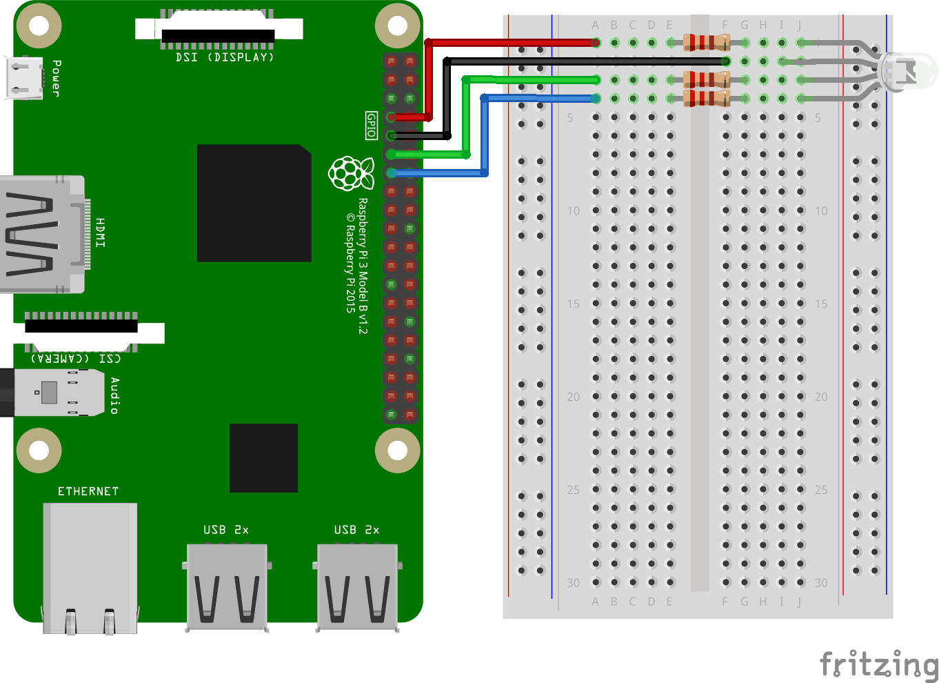
Look at the above illustration of the circuit.
- On the Breadboard, connect the RGB LED to the right ground bus column, and make sure that each leg connects to a different row. The longest leg is the common cathode leg. In this example we have connected the LED to rows 1-4, with the common cathode leg connected to row 2 column I. The RED leg is connected to row 1 column J, the GREEN leg is connected to row 3 column J, and the BLUE leg is connected to row 4 column J
- On the Raspberry Pi, connect the female leg of the first jumper wire to Ground. You can use any GND pin. In this example we used Physical Pin 9 (GND, row 5, left column)
- On the Breadboard, connect the male leg of the first jumper wire to the same row of the right ground bus column that you connected the common cathode to. In this example we connected it to row 2 column F
- On the Raspberry Pi, connect the female leg of the second jumper cable to a GPIO pin. We will use this for the RED leg, In this example we used Physical Pin 7 (GPIO 4, row 4, left column)
- On the Breadboard, connect the male leg of the second jumper wire to the left ground bus, same row as the RED leg of the LED is connected. In this example we connected it to row 1, column A
- On the Breadboard, connect a resistor between the left and right ground bus columns for the row with the RED leg of the LED. In this example we have attached it to row 1, column E and F
- On the Raspberry Pi, connect the female leg of the third jumper cable to a GPIO pin. We will use this for the GREEN leg, In this example we used Physical Pin 11 (GPIO 17, row 6, left column)
- On the Breadboard, connect the male leg of the third jumper wire to the left ground bus, same row as the GREEN leg of the LED is connected. In this example we connected it to row 3, column A
- On the Breadboard, connect a resistor between the left and right ground bus columns for the row with the GREEN leg of the LED. In this example we have attached it to row 3, column E and F
- On the Raspberry Pi, connect the female leg of the forth jumper cable to a GPIO pin. We will use this for the BLUE leg, In this example we used Physical Pin 13 (GPIO 27, row 7, left column)
- On the Breadboard, connect the male leg of the forth jumper wire to the left ground bus, same row as the BLUE leg of the LED is connected. In this example we connected it to row 4, column A
- On the Breadboard, connect a resistor between the left and right ground bus columns for the row with the BLUE leg of the LED. In this example we have attached it to row 4, column E and F
Your circuit should now be complete, and your connections should look pretty similar to the illustration above.
Now it is time to boot up the Raspberry Pi, and write the Node.js script to interact with it.
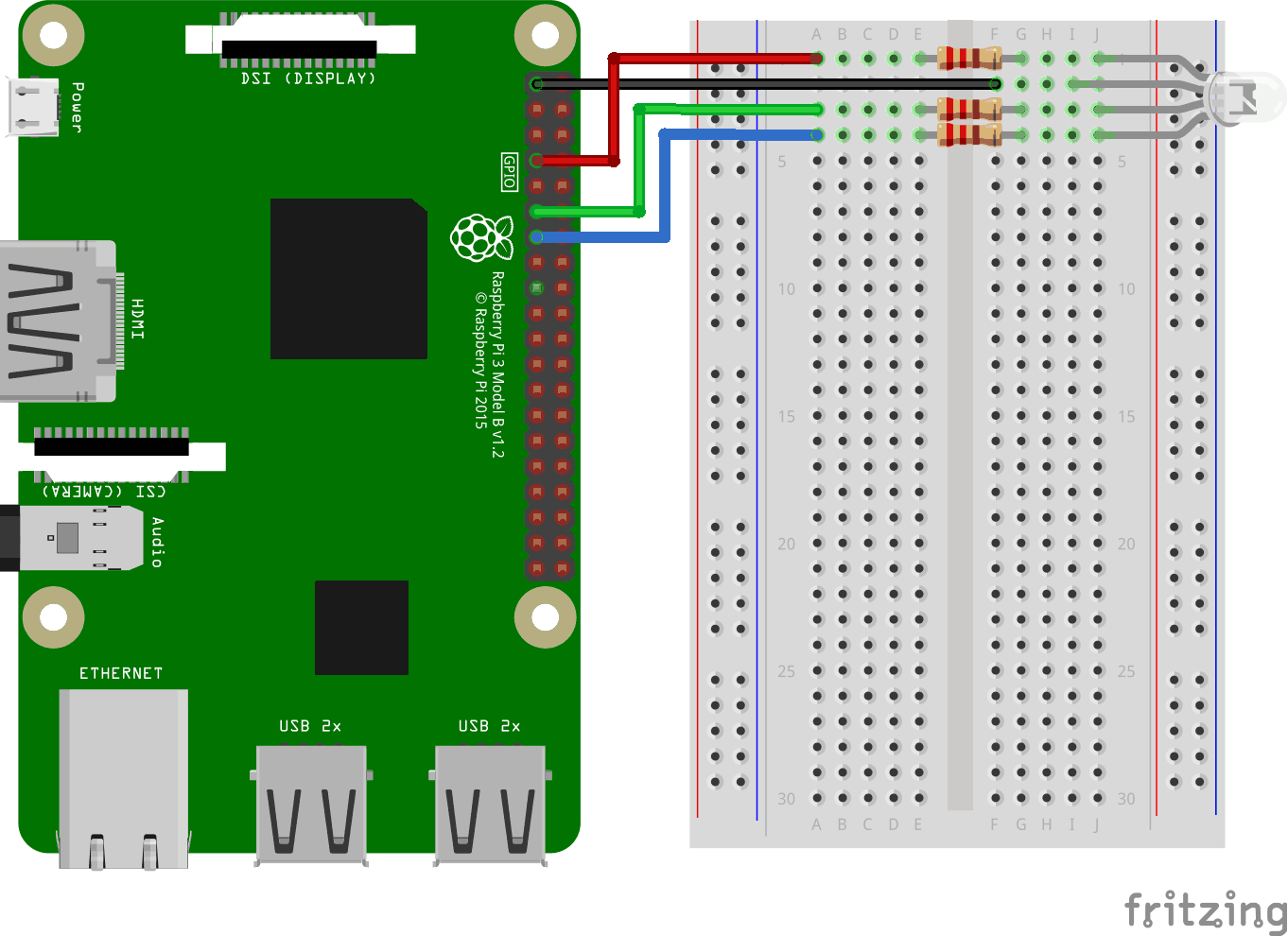
Look at the above illustration of the circuit.
- On the Breadboard, connect the RGB LED to the right ground bus column, and make sure that each leg connects to a different row. The longest leg is the common anode leg. In this example we have connected the LED to rows 1-4, with the common cathode leg connected to row 2 column I. The RED leg is connected to row 1 column J, the GREEN leg is connected to row 3 column J, and the BLUE leg is connected to row 4 column J
- On the Raspberry Pi, connect the female leg of the first jumper cable to a GPIO pin. We will use this for the RED leg, In this example we used Physical Pin 7 (GPIO 4, row 4, left column)
- On the Breadboard, connect the male leg of the first jumper wire to the left ground bus, same row as the RED leg of the LED is connected. In this example we connected it to row 1, column A
- On the Breadboard, connect a resistor between the left and right ground bus columns for the row with the RED leg of the LED. In this example we have attached it to row 1, column E and F
- On the Raspberry Pi, connect the female leg of the second jumper cable to a GPIO pin. We will use this for the GREEN leg, In this example we used Physical Pin 11 (GPIO 17, row 6, left column)
- On the Breadboard, connect the male leg of the second jumper wire to the left ground bus, same row as the GREEN leg of the LED is connected. In this example we connected it to row 3, column A
- On the Breadboard, connect a resistor between the left and right ground bus columns for the row with the GREEN leg of the LED. In this example we have attached it to row 3, column E and F
- On the Raspberry Pi, connect the female leg of the third jumper cable to a GPIO pin. We will use this for the BLUE leg, In this example we used Physical Pin 13 (GPIO 27, row 7, left column)
- On the Breadboard, connect the male leg of the third jumper wire to the left ground bus, same row as the BLUE leg of the LED is connected. In this example we connected it to row 4, column A
- On the Breadboard, connect a resistor between the left and right ground bus columns for the row with the BLUE leg of the LED. In this example we have attached it to row 4, column E and F
- On the Raspberry Pi, connect the female leg of the forth jumper wire to 3.3V. In this example we used Physical Pin 1 (3.3V, row 1, left column)
- On the Breadboard, connect the male leg of the forth jumper wire to the same row of the right ground bus column that you connected the common anode to. In this example we connected it to row 2 column F
Your circuit should now be complete, and your connections should look pretty similar to the illustration above.
Now it is time to boot up the Raspberry Pi, and write the Node.js script to interact with it.
Raspberry Pi and Node.js RGB LED and WebSocket Script
Go to the "nodetest" directory, and create a new file called "rgbws.js":
pi@w3demopi:~ $ nano rgbws.js
The file is now open and can be edited with the built in Nano Editor.
Write, or paste the following:
rgbws.js
var http = require('http').createServer(handler); //require http server, and
create server with function handler()
var fs = require('fs'); //require
filesystem module
var io = require('socket.io')(http) //require socket.io
module and pass the http object (server)
var Gpio = require('pigpio').Gpio,
//include pigpio to interact with the GPIO
ledRed = new Gpio(4, {mode:
Gpio.OUTPUT}), //use GPIO pin 4 as output for RED
ledGreen = new Gpio(17,
{mode: Gpio.OUTPUT}), //use GPIO pin 17 as output for GREEN
ledBlue = new
Gpio(27, {mode: Gpio.OUTPUT}), //use GPIO pin 27 as output for BLUE
redRGB
= 0, //set starting value of RED variable to off (0 for common cathode)
greenRGB = 0, //set starting value of GREEN variable to off (0 for common
cathode)
blueRGB = 0; //set starting value of BLUE variable to off (0 for
common cathode)
//RESET RGB LED
ledRed.digitalWrite(0); // Turn RED
LED off
ledGreen.digitalWrite(0); // Turn GREEN LED off
ledBlue.digitalWrite(0); // Turn BLUE LED off
http.listen(8080);
//listen to port 8080
function handler (req, res) { //what to do on
requests to port 8080
fs.readFile(__dirname + '/public/rgb.html',
function(err, data) { //read file rgb.html in public folder
if (err) {
res.writeHead(404,
{'Content-Type': 'text/html'}); //display 404 on error
return res.end("404 Not Found");
}
res.writeHead(200, {'Content-Type': 'text/html'}); //write HTML
res.write(data); //write data from rgb.html
return
res.end();
});
}
io.sockets.on('connection', function
(socket) {// Web Socket Connection
socket.on('rgbLed',
function(data) { //get light switch status from client
console.log(data); //output data from WebSocket connection to console
//for common cathode RGB LED 0 is fully off, and 255 is fully on
redRGB=parseInt(data.red);
greenRGB=parseInt(data.green);
blueRGB=parseInt(data.blue);
ledRed.pwmWrite(redRGB); //set RED LED to specified
value
ledGreen.pwmWrite(greenRGB); //set GREEN LED to
specified value
ledBlue.pwmWrite(blueRGB); //set BLUE
LED to specified value
});
});
process.on('SIGINT',
function () { //on ctrl+c
ledRed.digitalWrite(0); // Turn RED LED
off
ledGreen.digitalWrite(0); // Turn GREEN LED off
ledBlue.digitalWrite(0); // Turn BLUE LED off
process.exit(); //exit
completely
});
Press "Ctrl+x" to save the code. Confirm with "y", and confirm the name with "Enter".
Write, or paste the following:
rgbws.js
var http = require('http').createServer(handler); //require http server, and
create server with function handler()
var fs = require('fs'); //require
filesystem module
var io = require('socket.io')(http) //require socket.io
module and pass the http object (server)
var Gpio = require('pigpio').Gpio,
//include pigpio to interact with the GPIO
ledRed = new Gpio(4, {mode:
Gpio.OUTPUT}), //use GPIO pin 4 as output for RED
ledGreen = new Gpio(17,
{mode: Gpio.OUTPUT}), //use GPIO pin 17 as output for GREEN
ledBlue = new
Gpio(27, {mode: Gpio.OUTPUT}), //use GPIO pin 27 as output for BLUE
redRGB
= 255, //set starting value of RED variable to off (255 for common anode)
greenRGB = 255, //set starting value of GREEN variable to off (255 for common
anode)
blueRGB = 255; //set starting value of BLUE variable to off (255 for
common anode)
//RESET RGB LED
ledRed.digitalWrite(1); // Turn RED
LED off
ledGreen.digitalWrite(1); // Turn GREEN LED off
ledBlue.digitalWrite(1); // Turn BLUE LED off
http.listen(8080);
//listen to port 8080
function handler (req, res) { //what to do on
requests to port 8080
fs.readFile(__dirname + '/public/rgb.html',
function(err, data) { //read file rgb.html in public folder
if (err) {
res.writeHead(404,
{'Content-Type': 'text/html'}); //display 404 on error
return res.end("404 Not Found");
}
res.writeHead(200, {'Content-Type': 'text/html'}); //write HTML
res.write(data); //write data from rgb.html
return
res.end();
});
}
io.sockets.on('connection', function
(socket) {// Web Socket Connection
socket.on('rgbLed',
function(data) { //get light switch status from client
console.log(data); //output data from WebSocket connection to console
//for common anode RGB LED 255 is fully off, and 0 is fully on, so we
have to change the value from the client
redRGB=255-parseInt(data.red);
greenRGB=255-parseInt(data.green);
blueRGB=255-parseInt(data.blue);
console.log("rbg: "
+ redRGB + ", " + greenRGB + ", " + blueRGB); //output converted to console
ledRed.pwmWrite(redRGB); //set RED LED to specified
value
ledGreen.pwmWrite(greenRGB); //set GREEN LED to
specified value
ledBlue.pwmWrite(blueRGB); //set BLUE
LED to specified value
});
});
process.on('SIGINT',
function () { //on ctrl+c
ledRed.digitalWrite(1); // Turn RED LED
off
ledGreen.digitalWrite(1); // Turn GREEN LED off
ledBlue.digitalWrite(1); // Turn BLUE LED off
process.exit(); //exit
completely
});
Press "Ctrl+x" to save the code. Confirm with "y", and confirm the name with "Enter".
Raspberry Pi and Node.js WebSocket UI
Now it is time add the HTML that allows for user input via WebSocket.
For this we want:
- 3 color sliders, one for each color (RGB)
- A color picker
- A div showing the current color
Go to the folder "public":
pi@w3demopi:~/nodetest $
cd public
And create a HTML file, rgb.html:
pi@w3demopi:~/nodetest/public $
nano rgb.html
rgb.html:
<!DOCTYPE html>
<html>
<meta name="viewport"
content="width=device-width, initial-scale=1">
<link rel="stylesheet"
href="https://www.w3schools.com/w3css/4/w3.css">
<style>
.slider {
-webkit-appearance: none;
width: 100%;
height: 15px;
border-radius: 5px;
background: #d3d3d3;
outline: none;
opacity: 0.7;
-webkit-transition: .2s;
transition:
opacity .2s;
}
.slider:hover {opacity: 1;}
.slider::-webkit-slider-thumb {
-webkit-appearance: none;
appearance: none;
width: 25px;
height: 25px;
border-radius: 50%;
cursor: pointer;
}
.slider::-moz-range-thumb {
width:
25px;
height: 25px;
border-radius: 50%;
background: #4CAF50;
cursor: pointer;
}
#redSlider::-webkit-slider-thumb {background: red;}
#redSlider::-moz-range-thumb
{background: red;}
#greenSlider::-webkit-slider-thumb {background:
green;}
#greenSlider::-moz-range-thumb {background: green;}
#blueSlider::-webkit-slider-thumb
{background: blue;}
#blueSlider::-moz-range-thumb {background: blue;}
</style>
<body>
<div class="w3-container">
<h1>RGB Color</h1>
<div class="w3-cell-row">
<div class="w3-container w3-cell w3-mobile">
<p><input type="range" min="0" max="255" value="0" class="slider" id="redSlider"></p>
<p><input type="range" min="0" max="255" value="0" class="slider" id="greenSlider"></p>
<p><input type="range" min="0" max="255" value="0" class="slider" id="blueSlider"></p>
</div>
<div class="w3-container w3-cell w3-mobile" style="background-color:black"
id="colorShow">
<div></div>
</div>
</div>
<p>Or pick a color:
<input type="color" id="pickColor"></p>
</div>
<script src="https://cdnjs.cloudflare.com/ajax/libs/socket.io/2.0.3/socket.io.js"></script>
<script src="https://www.w3schools.com/lib/w3color.js"></script>
<script>
var socket = io(); //load socket.io-client and connect to the host that
serves the page
var rgb = w3color("rgb(0,0,0)"); //we use the w3color.js
library to keep the color as an object
window.addEventListener("load",
function(){ //when page loads
var rSlider =
document.getElementById("redSlider");
var gSlider =
document.getElementById("greenSlider");
var bSlider =
document.getElementById("blueSlider");
var picker =
document.getElementById("pickColor");
rSlider.addEventListener("change",
function() { //add event listener for when red slider changes
rgb.red = this.value; //update the RED color according to the slider
colorShow.style.backgroundColor = rgb.toRgbString(); //update the "Current
color"
socket.emit("rgbLed", rgb); //send the updated
color to RGB LED via WebSocket
});
gSlider.addEventListener("change", function() { //add event listener for
when green slider changes
rgb.green = this.value;
//update the GREEN color according to the slider
colorShow.style.backgroundColor = rgb.toRgbString(); //update the "Current
color"
socket.emit("rgbLed", rgb); //send the updated
color to RGB LED via WebSocket
});
bSlider.addEventListener("change", function() { //add event listener for
when blue slider changes
rgb.blue = this.value;
//update the BLUE color according to the slider
colorShow.style.backgroundColor = rgb.toRgbString(); //update the "Current
color"
socket.emit("rgbLed", rgb); //send the updated
color to RGB LED via WebSocket
});
picker.addEventListener("input", function() { //add event listener for when
colorpicker changes
rgb.red = w3color(this.value).red;
//Update the RED color according to the picker
rgb.green = w3color(this.value).green; //Update the GREEN color according to
the picker
rgb.blue = w3color(this.value).blue;
//Update the BLUE color according to the picker
colorShow.style.backgroundColor = rgb.toRgbString(); //update the
"Current color"
rSlider.value = rgb.red;
//Update the RED slider position according to the picker
gSlider.value = rgb.green; //Update the GREEN slider position
according to the picker
bSlider.value = rgb.blue;
//Update the BLUE slider position according to the picker
socket.emit("rgbLed", rgb); //send the updated color to RGB LED via
WebSocket
});
});
</script>
</body>
</html>
Return to the "nodetest" folder:
pi@w3demopi:~/nodetest $
cd ..
Run the code:
pi@w3demopi:~ $ sudo node rgbws.js
Note: Since the "pigpio" module uses the pigpio C library, it requires root/sudo privileges to access hardware peripherals (like the GPIO).
Open the website in a browser using http://[RaspberryPi_IP]:8080/
Now the RGB LED should change color depending on the user input.
End the program with Ctrl+c.
